Tuesday, 17 April 2012

Beginning Blue Tooth

I did my first bits of work on the blue tooth connection today. I'm using a FirePlug RN-USB-X blue tooth dongle along with a BlueSMiRF Modem connected to the Arduino.

BlueSMiRF modem
This is probably my favourite gadget so far - it's so neat and simple. It has it's address printed on the top so is easy to connect to, and acts just like a standard serial connection to the Arduino. Thus I can use the SoftwareSerial library with it, just like I did with the SpeakJet,which also communicated over a serial connection.

RN-USB-X dongle in my PC
The RN-USB-X is a very clever piece of kit in a very simple shell, ideal for robot builders anywhere. On connection it behaves exactly like a serial port - all setup is done by communicating with it via hyper terminal. Normally this would be annoying, but for robot making it's perfect, as I don't need any fancy software and I can write programs to configure it very easily (they just have to send text down the COM port). I spent a while getting it working, but that was mainly because the manual was hard to find and I initially tried to get one of the various Blue Tooth management apps that most dongles require. Serves me right - never look for the complicated answer first :)

One thing to remember if you get one of those dongles. The default baud rate for the modem is 115200 - make sure you set this in hyper terminal or it won't communicate.

Anyway, I get the dongle working and can talk to it via hyper terminal (you enter $$$ and it switches into config mode). Now it's time for the modem to be connected to the Arduino. It's got 6 pins:

  • Serial receive
  • Serial send
  • Serial ready-to-send
  • Serial ready-to-receive
  • Vcc
  • GND
Before trying anything fancy I just connect the GND and Vcc up so the modem has power. In theory I should now be able to connect to to it from my dongle plugged into the PC. Once powered up the LED flashes red, so I go back to hyper terminal. After a bit of reading documentation I type:

$$$
SR,80085389029383CC
SM,1
C

Obviously :) In english that's apparently enter config ($$$), set the receiver address (printed on the modem), set mode to 1 (master) so it can connect to things and finally 'C' to connect. To my amazement the LED on the modem turns green. Hurray!

The ready-to-send and ready-to-receive aren't essential, so if you don't bother with them (which I'm not), you just connect them together - that's the job of the blue cable in this close up:


The serial receive and serial send (yellow/green) connect to IO pins so the Arduino can communicate with the modem. Everything is now wired up and I've got a connection from PC to modem. Time for some Arduino code - this is a cut down version of my test:

#define bluToothRx 11
#define bluToothTx 12

SoftwareSerial bluTooth(bluToothRx,bluToothTx);

void setup()
{
Serial.begin(9600);   
bluTooth.begin(9600); 
}

void loop()
{
while(bluTooth.available())
{
Serial.write(bluTooth.read());
}
}

The idea is to send messages out to the Arduino over blue tooth, which then transmits it back over the serial connection to the PC. What I'm expecting is:
  • I type a message in hyper terminal
  • The message is sent through the blue tooth (disgused as a normal COM port) to the modem
  • The modem receives it, and passes it to the Arduino
  • The Arduino receives it, and sends it over the USB (serial) connection to the PC
  • Finally, the message finds it's way to the serial monitor in the Arduino which prints my message! 
Sounds like a lot of work to type in one window and see it appear in another, but if it works I know I can communicate over blue tooth.

It kind of works. When I run it and type a character in hyper terminal the signal gets piped into the Arduino, which then pumps it back to the PC. Unfortunately somewhere along the way all the characters are being changed to 255. Then it occurs to me that baud rate was an issue when getting hyper terminal to talk to the modem, so maybe that's the issue here. I take a guess that it's the same as the PC one (115200) , so my final code is:

void setup()
{
Serial.begin(9600);   
bluTooth.begin(115200); 
}

And lo and behold - it works! Here's a video to prove my awesome blue tooth message transceiver actually exists:


That's all for now. Next up - controlling the robot over blue tooth.

-Chris


Sensor Sweeps via Remote

So I've built a load of fancy circuitry and am just updating the PC code to be able to send commands to make use of all my new work (see the Going Remote post). This means my PC interface now has the following commands:


  COMMAND_KEEPALIVE,
  COMMAND_PING,
  COMMAND_MOTION,
  COMMAND_COMPASS,
  COMMAND_SAY,
  COMMAND_SET_SENSOR_POSITION,
  COMMAND_SET_MOTOR_SPEEDS,
  COMMAND_HORIZONTAL_SENSOR_SWEEP,


The final 3 are the new ones, the first 2 of which are fairly clear - they set the sensor platform position (x and y), or set the motor speeds (left and right). The sensor sweep however tells the arduino to move the sensor platform across an entire row, taking PING readings at fixed intervals. This returns you a list of up to 181 (0 to 180 degrees) individual readings.

This simple bit of c# code shows me sending commands to the Arduino to say hello, set some motor speeds and then move the sensor platforms to random locations.

        public void DoPortThread()
        {
            //open serial port
            SerialPort port = new SerialPort("COM7", 9600);
            port.Open();


            //clear any bytes waiting in it
            while (port.BytesToRead > 0)
                port.ReadByte();


            //say hello, then set motor speeds to 0
            SendSay(port, SPEECHMSG_HELLO);
            SendMotorSpeeds(port, 0,0);

            //start moving sensor to random locations
            Random r = new Random();
            while (true)
            {
                SendSensorPositions(port, r.Next(10,170), r.Next(60,100));
                Thread.Sleep(300);
            }
        }

And here's a video of the result:


Next up is the sensor sweep command which is a bit more interesting:


            for(int y = 45; y <= 100; y+=1)
            {
                ushort[] res = SendHorizontalSensorSweep(port,1);
                for (int i = 0; i < 1; i++ )
                   Dispatcher.Invoke(new Action(delegate { DoneSensorSweep(y+i, res); }), new object[] { });


                SendSensorPositions(port, 90, y);
                Thread.Sleep(300);
            }

This takes a sensor sweep on each row from orientation 45 to 100, and then tells the dispatcher to call 'DoneSensorSweep' on the main thread. This is basically a fancy way of just calling a function without stalling the UI in a Microsoft WPF c# application. 

I'll show the whole 'DoneSensorSweep' function, as it's quite interesting. It takes as parameters a row and the data that was recorded, then writes it into an image.

       public void DoneSensorSweep(int row, ushort[] data)
        {
            System.Diagnostics.Debug.Write("Scan " + row.ToString() + ": ");
            foreach (ushort d in data)
                System.Diagnostics.Debug.Write(d.ToString() + " ");
            System.Diagnostics.Debug.WriteLine("");

            // Reserve the back buffer for updates.
            WriteableBitmap.Lock();

            int pixels_per_data = 180 / (data.Length - 1);

            unsafe
            {
                // Get a pointer to the back buffer.
                int pBackBuffer = (int)WriteableBitmap.BackBuffer;
                pBackBuffer += row * WriteableBitmap.BackBufferStride;
 
                // Find the address of the pixel to draw.
                int col = 0;
                foreach(ushort val in data)
                {
                    for (int i = 0; i < pixels_per_data; i++)
                    {
                        int pix = pBackBuffer + col * 4;
                        int greyscale = 255 - (val/2 <= 255 ? val/2 : 255);
                        int color_data = greyscale << 16; // R
                        color_data |= greyscale << 8;   // G
                        color_data |= greyscale << 0;   // B
                        *((int*)pix) = color_data;
                        col++;
                    }
                }
            }

            // Specify the area of the bitmap that changed.
            WriteableBitmap.AddDirtyRect(new Int32Rect(0, row, 181, 1));

            // Release the back buffer and make it available for display.
            WriteableBitmap.Unlock();
        }

The final result is a screen shot like this:


Believe it or not, that's an ultra sound scan of a chair on a stool. Don't beleive me? Check this out:


OK it's not exactly computer vision, and I'll definitely be adding colour stereo cameras soon, but even in this raw unprocessed form it is.. well... cool :)

Next up, I've got my blu tooth modem + dongle now, so will try doing some stuff wirelessly!


Monday, 16 April 2012

Dual Axis Sensor Platform

Short post here - not quite ready to put the whole robot together yet, but I fancied building something, so I've put together this prototype for a sensor platform:


It's built from 2 servos, some glue, a load of balsa wood and a random long bolt I had. The bread board that has ping/motion sensors then gets taped on top. While it's not exactly beautiful and has quite a few issues, it does do the job. I get 2 axis of movement, so I can point the sensors in any direction and take a reading.

The code to make this work is very simple, and made even simpler by the Arduino libraries. In case you don't know, most servos are basically:
  • A motor and gearbox
  • A feedback system, so the servo knows what angle it is currently at
  • An input to connect to the micro-controller so you can tell it what angle to use
Most of the time servos are designed to be given an angle to move to - i.e 'move to 60 degrees', although you do get continuous rotation ones that give speed control instead of angle. Either way, servos are really easy to hook up, as you can see from this circuit:


Here we have the basic setup - each servo is powered off a battery, and as always they share the same ground with the Arduino. The signal inputs for each servo are then plugged into IO pins. I'm thinking maybe there should be a resistor in between to minimize current draw from the Arduino, but I'll check that out with the Ammeter next time I'm using it.

To control a digital servo you simply send it a square wave - a PWM (pulse width modulation) signal. Fortunately the Arduino has built in support for PWM, and also comes with a handy 'servo library' that wraps up all the nasty bits, allowing you to write code like this:

#include <Servo.h>
Servo sensorservo;
Servo sensorservo2;
#define servoAPin 3
#define servoBPin 9

void setup()
{
  sensorservo.attach(servoAPin);
  sensorservo2.attach(servoBPin);
  sensorservo.write(90); //move sensor servo A to 90 degrees
  sensorservo2.write(90); //move sensor servo B to 90 degrees
}

I'm guessing (although I haven't tried) that the pins you give to a servo controller need to be PWM pins, so the servo keeps getting a signal. That's a guess though - should probably try it out and see - maybe the servo doesn't need a continuous signal?

After a bit of fiddling I add a bit of code that goes through every possible angle, as though it's doing a sensor sweep and here's the result - if video broken it's here etc bla bla bla :)


Next, at each orientation I add the code to take  PING distance reading and print the value out to serial. This gives me a raw list of numbers I can copy and paste into excel, yielding....


This is a sensor sweep repeating 3 times. The graph shows the distances that the PING sensor detected as it scanned from left to right across the room. Once the PC is doing the work I should be able to build up a 2D image using the 2 axis sensor platform - Yay!

Few basic conclusions I came up with from the prototype:
  • Need to make sure the sensors (especially PING) aren't obscured at any orientation by the stand itself
  • Dual axis is awesome and well worth it and also cool
  • Ideally the sensors are fairly high up, so half of what you see isn't just the floor
  • High potential for cuteness provided whatever is on the platform looks like eyes....
  • The servos need to be as close together as possible, to avoid angular changes affecting the physical position of the sensor
That's it for now - hopefully building robot soon. In the mean time I'll probably get things working nice and remotely (i.e. so my PC can control everything) so I can write a bit of fancier code


Sunday, 15 April 2012

Big Fat Motors!

Well, I've been waiting for ages for some sabre tooth motor controllers and they've still not arrived in the post, but I do have some very chunky motors sitting here:

Chunky Motor
Rather than wait for ages for them, I've decided to build my own very simple motor controllers with a bit of help from this tutorial. After experimenting with the example for a bit I end up with this circuit to drive my 2 motors:

Arduino controlling 2 motors, powered off 4.5v battery.
Different power sources (Arduino and battery) are connected to same GND

If you ignore the capacitors and diodes for the moment, all you have here is 2 motors connected to a 4.5v battery via the 2N7052 transistors. These transistors only allow current to flow if they receive a signal from the Arduino.via one of the GPIO Pins (with a couple of 10k resistors to minimize current flow).

The capacitors and diodes are there to protect the circuit against some annoying properties of motors. The spinning motor creates noise, and (as I understand it), the capacitor absorbs spikes by acting as a cushion, and the diode prevents current reversal by acting as a valve. That's my understanding though - might find out I'm wrong a few posts later :)

Here's my circuitry as it stands with the motors now hooked up to the rest of the circuitry:

Motors connected to arduino via motor controllers

This close up shows 1 of the motor controllers on the bread board

Motor Controller Closeup
Only tiny prob with this photo is that I originally used the wrong capacitor, so you should see a much smaller (probably rectangular) one there. Things all worked though as that circuit is just for protection really - I should think the circuit would run with neither, it just wouldn't live as long!

I now send alternate HIGH/LOW signals to the motor pins once per second and watch as the motors turn on and off, however this isn't too interesting, so I add some wheels to the motors - big, chunky wheels :)


I get the wheels turning alternately and it looks great and Dave sees it and makes an impressed noise which is always a good sign. Next I experiment with getting the left one to run more slowly by sending it a square wave (i.e. pulses of current) rather than a solid signal. This definitely works, but as I'm running the motors at significantly below power already (they're 12-18V motors), any significant drop in current just stops them running. This technique'll be much more effective when there's a higher voltage going in.

As a quick test to prove the point of the transistors, I hook up an ammeter - first in series with the Arduino and transistor, then later in series with the motor and battery. Ideally what we should see is the Arduino having to provide a very low current in order to allow a lot of current to flow from battery to motor.


On the left you see the reading coming out of the Ardiuno - a tiny 0.35mA - well within Arduino operating range. However on the right you see our 4.5V batteries pumping out 156mA of current, which will probably be closer to 1A by the time we've got full power batteries and proper motor controllers in - I'm starting to see why they recommend cut off switches!

So that's the lot for motors - all fun and games. Here's a final video of it in action responding to sensor input and turning motors. Blogger seems to have been having issues with it lately, so if the vid doesn't work check it out on you tube here:


Blog is almost caught up with real world now! Next one will be about my prototype dual axis sensor platform

-Chris

Saturday, 14 April 2012

Going Remote

The Arduino IDE has been getting on my nerves and despite being cool, the chip itself isn't really powerful enough to do some of the things I want to do (like face recognition). Hence I'm going to take a quick step to turn my computer into the brain. This post is just code - it's about moving where the software runs.

We've already got all the sensors and SpeakJet connected so now I just add some utility functions to send and receive data over the serial interface:


void WaitForBytes(int count)
{
  while(Serial.available() < count) {}
}


int ReadWord()
{
  WaitForBytes(2);
  return Serial.read() | (Serial.read() << 8);
}


void WriteWord(int data)
{
    byte highbyte = data >> 8;
    byte lowbyte = data & 0xff;
    Serial.write(lowbyte);
    Serial.write(highbyte);
}


Create a list of potential commands:


enum ECommands
{
  COMMAND_KEEPALIVE,
  COMMAND_PING,
  COMMAND_MOTION,
  COMMAND_COMPASS,
  COMMAND_SAY,
  TOTAL_COMMANDS
};


Next I turn the loop into a switch statement that simply waits for a command id to be sent over remotely, acts on the command and finally sends a response:


/**
 */
void loop()
{ 
  if(Serial.available() > 0)
  {
    int command = Serial.read();
    switch(command)
    {
      case COMMAND_PING:
      {  
        int data = readUltraSound();
        WriteWord(data);
        break;
      }
      case COMMAND_MOTION:
      {  
        int data = readMotion();
        WriteWord(data);
        break;
      }
        //.............
        //Other commands here 
        //............
  }
}

Here you can see the ping test which takes an ultra sound reading then sends back a distance. The motion sensor does exactly the same thing, sending back a 1 if motion is detected, 0 if not. 

The speech command was a little more interesting, as the PC needed to be able to send what to say. My first version just takes a message length, followed by a series of bytes to send directly to the Speak Jet:

        int count = ReadWord();            //read byte count
        Serial.print("Say bytes: ");
        Serial.print(count);
        Serial.print(":");
        WaitForBytes(count);               //wait for message to arrive in full
        for(int i = 0; i < count; i++)
        {
          uint8_t data = Serial.read();    //read byte
          speakjet.AddByte(data);          //send directly to speak jet
          Serial.print(data);
          Serial.print(",");
        }
        speakjet.Wait();                   //wait for speech to finish
        Serial.println("");                //print newline to tell pc its done
        break;

Note that the final step is to wait until speech is complete and then a print a new line, which is allows the PC to block until speech is complete. If I need to get fancier I can add extra data, like whether to do the final wait and respond step.

The PC code is just communicating over a standard COM port. I decide to start with c# as it's quick and simple, and I don't have anything massively powerful in mind yet - it'll be easy to switch to C++ later though. (Will post a bit of code here soon). 

The advantage of this setup is that I can now easily write lots of prototype code on my PC, where the bulk of my robot's thinking will occur and I can monitor what's going on. The Arduino now acts as a slave to the PC, executing commands on demand. Algorithms that become time critical can be embedded as new commands.

That's about it for now. Eventually I'll connect via blu tooth, but some postal issues appear to have delayed my modem so we'll see. Next up, some motors.


Friday, 13 April 2012

Saying Measurements

One more post about the speak jet and an intro to the compass. Plan is to take measurements and then read them out. Before doing this I decide to try and create an Arduino library to manage the speak jet interface. Doing this was a nightmare in the Arduino IDE, but after bit of coding and a lot of messing around I had this interface:


class CSpeakJet
{
public:


  CSpeakJet(uint8_t receive_pin, uint8_t transmit_pin, uint8_t is_speaking_pin);
  
  void Begin();
  void SetVolume(int lVol);
  void SetPitch(int lPitch);
  void SetSpeed(int lSpeed);
  void SetBend(int lBend);
  void Play(uint8_t* data, int len, bool wait);
  void Play(int id, bool wait);
  void PlayNumber(int number, bool wait);
  void AddByte(uint8_t data);
  void Wait();
  
private:
  SoftwareSerial mSerial;
  uint8_t mSpeakingPin;
};


This class provides functions to set volume/pitch/speed/bend, and a 2 ways to play a sound. The first simply sends a series of bytes to the speech jet. However the second takes an index into a hard coded list of sounds:


enum ESpeech
{
 SPEECH_HELLO,
 SPEECH_YOUR,
 SPEECH_ENGINE,
 SPEECH_IS,
 SPEECH_BOUNCY,
 SPEECH_I,
 SPEECH_CAN,
 SPEECH_SEE,
 SPEECH_YOU,
 SPEECH_DEGREES,
 SPEECH_ANGLE,
 SPEECH_DISTANCE,
 SPEECH_0,
 SPEECH_1,
 SPEECH_2,
 SPEECH_3,
 SPEECH_4,
 SPEECH_5,
 SPEECH_6,
 SPEECH_7,
 SPEECH_8,
 SPEECH_9,
 TOTAL_SPEECH 
};

In amongst these are the numbers 0 to 9. All that needs to happen now is a simple function to extract the digits of a number and say them, rather like converting numbers to strings. After a bit of fiddling I come up with this, which could be better but does the job for now:

void CSpeakJet::PlayNumber(int number)
{
  int orignumber = number;
  if(orignumber >= 1000)
    Play(int(SPEECH_0+number/1000));
  number = number % 1000;
  if(orignumber >= 100)
    Play(int(SPEECH_0+number/100));
  number = number % 100;
  if(orignumber >= 10)
    Play(int(SPEECH_0+number/10));
  number = number % 10; 
  Play(int(SPEECH_0+number/1));
}

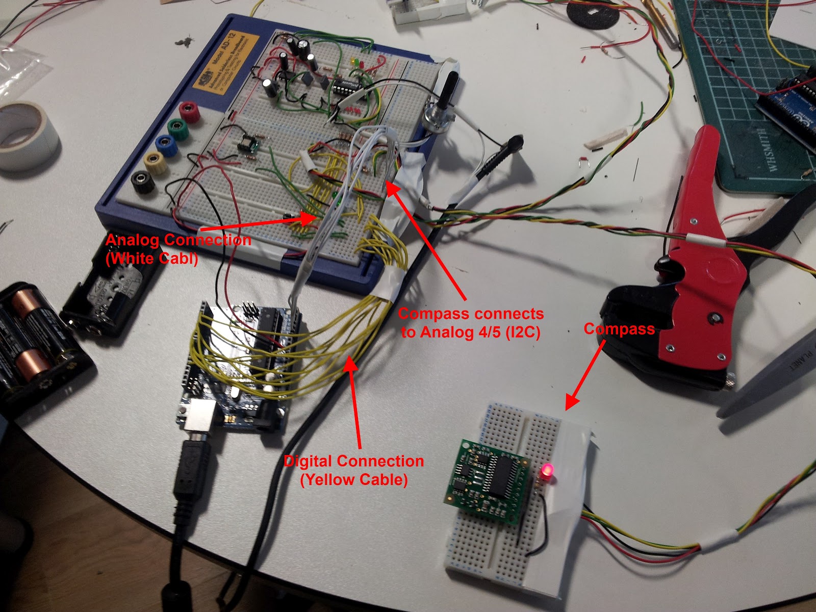
Next up it's time to connect the CMP03 electronic compass. I introduced this device in the Bob The Boe Bot post earlier. However it wasn't massively useful, as it communicated using pulse width modulation which was too slow. This time we'll be hooking it up via an I2C Bus, as shown below.


Compass with I2C connection

Developed by Philips, this clever system is a common way for multiple devices to communicate with a microcontroller, normally in master/slave configuration. The master can choose to send a message to one of the devices on the network and sends it's address down the data line, followed by the data. It then waits while the slave sends a response. It's too much to explain right now but there's lots of info here. If you're starting to robot you'll need this soon.

Compass connected to I2C via Analog pins

The Arduino has built in support for I2C and can act as master or slave. On the Uno this is done using  Analog Pins 4 and 5, along with a library to send and receive data through it.

Arduino devices, now with CMP03 Compass

Here you see the circuit from the last blog which includes PING, Motion and Speak Jet, now with an added Compass connected via I2C to Analog In 4+5 on the Arduino. Using the Wire library we can then communicate with the compass using a hardcoded address that the sensor stores.


//read value from 0 to 359 degrees

#define ADDRESS 0x60 //defines address of compass


int readCompass(){
  byte highByte;
  byte lowByte;
  
   Wire.beginTransmission(ADDRESS);     //starts communication with cmps03
   Wire.write(2);                       //Sends the register we wish to read
   Wire.endTransmission();
   Wire.requestFrom(ADDRESS, 2);        //requests high byte
   
   while(Wire.available() < 2);         //wait for 2 bytes
   
   highByte = Wire.read();              //reads the bytes as a integers
   lowByte = Wire.read();
   return ((highByte<<8)+lowByte)/10;   //combine and return 16 bit integer
}


With a bit of work, I plug all the bits together to get:

  • Wait until button clicked
  • Read compass and ping sensor
  • Say 'Compass'
  • Using PlayNumber function I wrote earlier to say the compass reading
  • Say 'Distance'
  • Use PlayNumber again to say the distance reading

And here's a little video of it in action (if vid doesn't work, check on you tube here):


And there you have it - the Arduino using a SpeakJet to read out measurements from a compass and ultra sound sensor when 

SpeakJet and Sensors

I finished off the last post with a working speak jet which can be sent commands to say stuff or change pitch/speed/bend/volume. However all it could do was repeat the same phrase once per second. The obvious next step is to get it responding to sensors. Well actually the next step was to make it tell Dave his physics engine was bouncy every second, but that's another story. I've not got much code here as I changed a lot by the time I wrote this post.

I download the SpeakJet software which has a little dictionary of common words and work out the commands to make it say 'I Can See You' in a spooky robot voice, then change the pitch based on the reading from the ping sensor. Both the PING and motion sensor are plugged in, so we now have this circuit (I've left off some of the less relavent connections to the speak jet to keep it simple):


PING, Motion and SpeakJet connected to Arduino
RCX (serial) is connected to GPIO3

Changing the pitch is quite simply a case of sending the SpeakJet a pitch change command (22), followed by a number from 0 to 255 (although 100 to 255 seem to work more effectively). Since the ping sensor is plugged in, all I need to do is modify the code to:
  • Read the PING sensor value
  • Map it to a range between 100 and 255
  • Send the pitch change command to the new value
  • Send commands to say the message
This works wonderfully, and I proudly show Dave, who promptly declares it's just not worth doing unless the pitch can change for every word, not just the whole phrase. This seems easy and I change the code to read the sensor and set pitch before each word. However there is a problem with this approach - it doesn't work. This is because I'm attempting to send all the commands at once. It's true that I take a reading from the ping sensor before each word, but in the real world what's happening is:
  1. Read PING and set pitch
  2. Send say 'I' command
  3. Read PING and set pitch
  4. Send say 'Can' command
  5. Read PING and set pitch
  6. Send say 'See' command
  7. Read PING and set pitch
  8. Send Say 'You' command
  9. Speak jet says 'I Can See You'
The first 8 steps take less than a few ms to execute as we're just reading ping values and sending commands. Hence all the readings come out roughly the same. What we actually needed was:
  1. Read PING and set pitch
  2. Send say x command
  3. Wait for Speak Jet To Finish Saying It
  4. Read PING and set pitch
  5. etc etc etc
So how do I know when the speak jet has finished talking? Well, remember the extra output pins on the speak jet - Ready, Speaking and Buffer 1/2 full? If I connect the Speaking pin back into the Arduino I will be able to detect when the Speak Jet is actually saying words. The circuit modification is very simple:

Add caption


And with a bit code to add the wait it works! After each word is said the pitch will be set base on how close something is to the ping sensor. This video demonstrates it quite nicely (if vid broken check here):


All good! Now for one final trick I hook up a push button to the code that can be hit to say hello just for fun (if broken check here):


I spend the rest of the day neatening up my wiring so it's not a hideous mess of knots and tangles and will actually fit in a robot when I put it there.

-Chris