Monday 30 April 2012

Eyes and a Head

I now have cameras working and a robot that can move around. A week or 2 ago I built a prototype sensor platform, but now it's time for the real deal. Well, another prototype for the real deal. Actually another 2 prototypes for the real deal. But my latest prototype rocks! It's time to take those 2 LinkSprite cameras and mount them on their own axis, on top of a head with a proper neck.

After much pondering, I decided one of the keys to cuteness is the eyes, and crucially that they can each swivel on their own axis just like human eyes do. That doesn't mean they'll move independently (which would be creepy), but they need to rotate just like eye balls do. So looking left means each eye turns left on it's own axis. Human eyes can actually look up/down/left/right, but that would be really tricky, so I've decided to focus on just horizontal movement.

I start off by making a very simple prototype with absolutely no planning whatsoever. The cameras need to be mounted on something, so I build 2 small square frames out of balsa wood. As always, I can't find any suitable bolts with which to attach the cameras, so I improvise, and paper clips become my preffered means of attachment. They work ridiculously well, and I gain a new found respect for the wonder of paper clips.

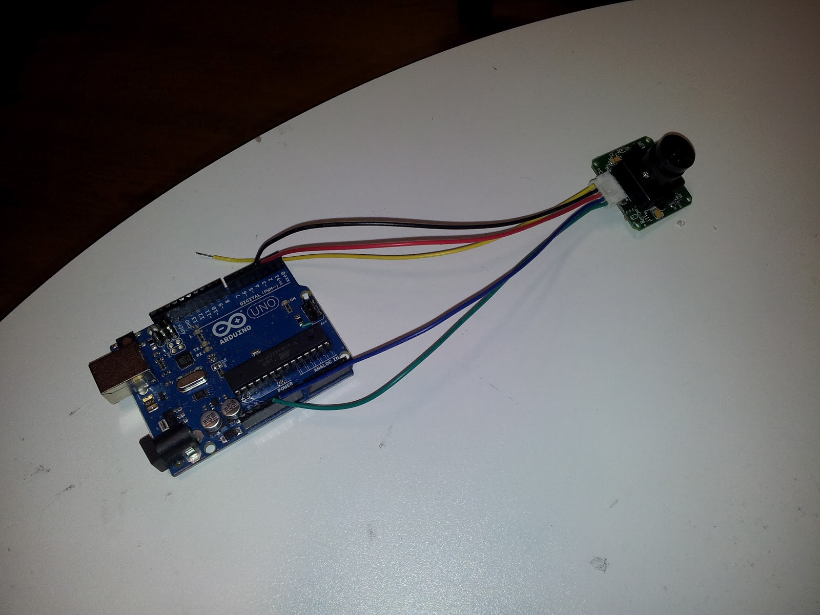
Early prototype eye frame with cameras rotating around an axle made of a bendy metal rod

Next up, I glue a small bit of wood to the back of each camera mounting and drill a vertical hole through which I stick a bent piece of metal somebody left on my desk (when I sent an email round asking for bendy pieces of metal).

Rear view of prototype, with paper clip lever mechanism to make eyes rotate in unison 

Now building on my new love of paper clips, I straighten 2 out and attach them so they stick out of the back of the wooden mounts and can act as levers. When the levers are pushed left/right, they cause the wood to rotate, which in turn causes the cameras (aka eyes) to turn left and right. As one final step I use another paper clip to join the 2 horizontally (the yellow clip above). Now when this horizontal bar is pushed left or right, both eyes will rotate in unison!

The mechanism is wobbly, but it proves a point. This was still Saturday night and I'd done a hard days debugging of camera code, so I decide to end it there and ponder how to build a proper frame over a good nights sleep...

Ok, through the magic of writing it's now Sunday and I have a good idea of how this mechanism actually needs to work. The wooden camera mounts are good, but the pivots need to be directly above and below the cameras rather than behind them. First things first, I load up visio and properly design the camera mount with measurements and everything:


This new design will be much more robust, as the cameras are held on from above and below. They'll still be attached to the same wooden mounts, but I will attach these to a frame with some small metal axles. To turn the eyes I'll use a lever mechanism driven by a mini servo (taken from John's ex-radio-controlled-helicopter) which will be glued to the same frame.

So, armed with a design, I cut up some bits of wood to build the initial frame:

Eye frame cut and axles attached to the camera mounts, ready for fitting together

You can see it taking shape above. The small 'axles' are simply pieces of an aluminium rod someone gave me earlier, chopped up with my Dremmel (causing a lot of sparks). It's not too interesting but I'm proud of my metal cutting, so here's a photo of the chopped up axles:

My beautifully cut aluminium axles (plus my lovely Dremmel)

Right. I have my frame and I have my axles. Time to glue the axles to the camera mounts, create a couple of holes in the frame, add some washers and check things rotate as expected.

Eye frame put together with servo mounted in the middle

As you can see here, everything fits together just right (thanks to actually designing it in advance), and I glue the servo in between the 2 cameras. A subtle but crucial point is that the servo lever is positioned so that it's pivot is at the same depth as the pivots for the 2 cameras. This keeps things simple, as I'll get a 1-to-1 relationship between servo rotation and camera rotation.


Next up, I canibalize some more of John's old helicopter, which is full of handy levers that are strong and have adjustable lengths. I attach small pieces of wood to the back of the camera mounts, drill tiny holes in them and glue 2 of the shortest levers so they stick out the back. Next, I extend the servo lever using another paper clip, bent to fit rigidly through the holes on the servo lever.


Helicopter levers and paper clips to make rear mechanism that turns the eyes

All I need now is to take a couple more of the levers from the helicopter and attach them horizontally so they meet in the middle and join the extended servo lever (aka paper clip). That's the basic mechanism built - if I twist the servo lever left or right, it forces the horizontal lever left or right. This in turn pulls the levers attached to the mounts, which then rotate on their axles. The frame isn't actually held together by anything yet, but aside from that I have a working eye frame.

Next up, I effectively just build a box around the working eye frame, which turns it into a more robust and properly held together head. This is a pretty crucial point, as it'll be hard to dismantle if I get things wrong so before going ahead, I retest both cameras and the servo. All seem to be good so I build the head and wire it up to my Arduino Uno and write a simple program to get the eyes looking around:


Now for a neck. I learnt from my earlier experiments with the sensor platform that it's entirely possible to build a 2 axis system using 2 servos. However the servos need to be as low as possible, ideally both below the sensors (so they don't obscure anything). With this in mind I decide to go for the simplest possible design, and pretty much attach 2 servos to each other with a single piece of wood.

Servo attached to wood, with second servo disk embedded in wood and way too much epoxy resin! 

You can see here 1 servo glued to some wood with epoxy resin, and another servo disk embedded in the wood and glued in with rather too much resin. All I need to do is attach the servo disk to the second servo, and I have a 2 axis neck.

Finally, I take a large, flat piece of wood and cut out the shape of a servo disk to attach the upper servo. This flat piece of wood is then bolted onto the bottom of the head as you can see below:

Fully constructed neck and head

The bottom servo makes the head look up/down, while the upper servo turns it left/right. On top of that is the head itself with the eye frame and it's mini servo to turn the eyes left and right.

Some more epoxy and an Aluminium A-frame later, I have the neck attached to the front of MmBot:

Neck and head attached to MmBot

I was admittedly winging it a little bit at this point, but everything's gone fairly well so far. The only minor hindrance was that the bolts to attach the A frame needed to go through one of the aluminium reinforcements on the inside of the robot. Dave doesn't mind a bit of drilling in the background though, so I get out the old Black-And-Decker and attach a metal drill bit. In not too much time it's all bolted together and is pretty solid.

Just one more step... time for some testing! I connect all the servos to the prototyping board inside MmBot and run a simple test program to set the servos to random positions. Here it is in action:


And there you have it! A full blown 2 axis neck, controlling a head with independently mounted eyes. Let no man look at MmBot now and say she isn't cute!

What a great day :) Next up I'll get the cameras wired into the Arduino and start sending signals via blue tooth to/from the pc. Shouldn't be long before MmBot is combining  fully articulated joints with cameras and face detection to make eye contact with real people!

-Chris

Sunday 29 April 2012

A quick camera api

By about 6 on Saturday I fully understood the cameras and had them communicating properly, so I decided to write a proper api for them, and test them in full. There's been a bit too much code on this blog lately so I don't want to spend too much time on it, but it's worth mentioning, especially as this might be useful to anyone trying to do the same thing.

This class shows my basic camera api:


class CCamera
{
public:

    CCamera();
    bool Begin(HardwareSerial* serial);
    bool Begin(SoftwareSerial* serial);
    bool Update(); //returns true if idle after update
    bool IsDone();
    ECameraState GetState();
    bool Wait(unsigned long timeout_ms=0); //pass 0 for 'infinite'
    bool Reset();
    bool StartTakingPicture();
    bool GetFileSize(unsigned long* size_buffer);
    bool GetContent(uint8_t* buffer, unsigned long* amount_read_buffer, unsigned long bytes, unsigned long address);
    bool StopTakingPicture();
    bool SetDimensions(ECameraImageDimensions dims);
    bool SetCompressionRatio(unsigned long ratio_0_to_255);
    bool EnterPowerSaving();
    bool LeavePowerSaving();
    bool SetBaudRate(ECameraBaudRate rate);
        
private:
    //... member variables here
};


Download the full code here: camera.zip

You start it up by passing a hardware or serial interface, and can then give it commands to execute. Each command simply posts a request to the camera. Once posted, you keep calling 'Update' until it returns true. This allows you to use the camera in a none-blocking manner which will be needed for MmBot, as she needs to be able to do multiple things at once and never stop responding. In the event that you do actually want to block until a command is ready, you simply call 'Wait' which will internally just keep calling Update until it's done. This little snippet shows me using the 'GetContent' function to read from camera and print it to Serial1 (which has the blue tooth connected to it!):


  while(address < fsize)
  {  
    //read data
    Camera.GetContent(buffer,&amount_read,32,address);
    Camera.Wait();
    
    //print data
    for(int i = 0; i < amount_read; i++)
    {
      printbyte(buffer[i]);
      Serial1.print(",");
    }
    Serial1.println("");
    delay(100);
    
    address += amount_read;
  }      

I got all commands working, however setting the baud rate is tricky (as you then have to change the baud rate you try and talk to it at, and then restarting confuses things etc etc). I also noticed a slight oddity with the cameras - changing compression ratio takes a few images to take effect, so don't be surprised if you set it to highly compressed and your images don't get smaller for a few frames. I think this is just a property of the LinkSprite cameras though.

One thing I have realised after much experimentation is that I'm not gonna be getting more than 1fps out of this, so the pc based image processing will be limited until my raspberry pi arrives (at which point I can use high speed web cams and process them without needing to transmit across a network).

OK, that's enough for this quick little post. Cameras are now fully functional, and I've managed to send data across blue tooth back to the pc. Next up it's time to build the eyes and head.

-Chris

Saturday 28 April 2012

Cameras - 42 not 37

Well, as my last post detailed, I got a certain distance with cameras and then hit a brick wall trying to get hardware serial communications working. I've decided as my next step to get the much simpler linksprite sample code and get it working on an Arduino Uno.

The LinkSprite sample just consists of a few functions to send specific commands to the camera - reset, take photo and read data. Internally these quite literally just pump bytes of data down the serial port (they don't even wait for a response). The read data one is the only slightly clever bit, as it sends the address it wants to read as well. I won't bother showing these ones though. What is here, is my cleaned up and made useful version of the main loop:

void loop() 
{
  //send reset command
  SendResetCmd();
  delay(4000);                              
 
  //send take photo command
  Serial.println("Taking photo");
  SendTakePhotoCmd();

  //drain any bytes out of the serial buffer that will have come back from the previous 2 commands
  while(mySerial.available()>0)
  {
    incomingbyte=mySerial.read();
    printbyte(incomingbyte);
  }   
  Serial.println();
  
  //begin reading the photo
  Serial.println("Reading data");
  while(!EndFlag)
  {  
    //send command to read data
    SendReadDataCmd();
    
    //delay 25ms - and just hope data arrives within this time??   
    delay(25);
    
    //read whole response (5 byte response+32 byte data) into 'all' buffer
    int pos=0;
    int count=0;
    byte all[64];
    while(mySerial.available()>0)
    {
      //get response
      all[pos]=mySerial.read();
      
      //if within the actual data range
      if((pos>5)&&(pos<37)&&(!EndFlag))
      {
        //check for EOF marker (0xFF followed by 0xD9)
        if((all[pos-1]==0xFF)&&(all[pos]==0xD9))      //Check if the picture is over
          EndFlag=1;                           
        //increment bytes read count
        count++;
      }
      
      //move forwards 1 byte
      pos++;
    }
    
    //check we actually got data
    if(pos > 0)
    {
      //print out the response bytes (should always be 0x76 0x00 0x32 0x00 0x00)
      for(j=0; j < 5; j++)
      {
         printbyte(all[j]);
      }
      Serial.println();
      
      //print out the data bytes
      for(j=0;j<count;j++)
      {   
         printbyte(all[j+5]);
      }                                       //Send jpeg picture over the serial port
      Serial.println();
    }
    else
    {
      //if didn't get anything, print a warning
      Serial.println("No data!");
    }
  }      
  while(1);
}

If you've done much communications code the first thing you might see and scream in horror at is the delay(25) just after reading data. This classic noob error is basically assuming that after 25ms the data will definately be around nice and ready to use. Still, I decide to not change any key logic yet. What I do change is what gets printed. The purpose of this round is to debug what's going wrong, so rather than try to get nice images across, I print out every command response, followed by the data it provides.


Taking photo
0x76 0x00 0x26 ... response from first commands ... 0x36 0x00 0x00 
Reading data
0x76 0x00 0x32 0x00 0x00 
0xFF 0xD8 0xFF ... image data ... 0x00 0x0D 0x00 
0x76 0x00 0x32 0x00 0x00 
0x12 0x0B 0x51 ... image data ... 0x08 0x05 0x05 
0x76 0x00 0x32 0x00 0x00 
0x04 0x05 0x0A ... image data ... 0x12 0x13 0x14 
0x76 0x00 0x32 0x00 0x00 
0x15 0x15 0x0D ... image data ... 0x14 0x14 0x14 


What you see here is the initial photo being taken, followed by me draining all data from the serial buffer. Then I begin reading data in 32 byte chunks. Each read returns a response (0x76 0x00 0x32 0x00 0x00) followed by 32 bytes of image data. All good, but already just by searching through the log I see some weirdness:


0x76 0x00 0x32 0x00 0x00 
0xC4 0x2D 0x82 ... image data ... 0x54 0x75 0xAB 
0x76 0x00 0x32 0x00 0x00 
                                <---- where's the image data?
0x90 0x34 0xC5 0xB3 0x51        <---- and this is not a good response! 
0xB1 0x2D 0xD7 ... image data ... 0x00 0x32 0x00 
0x76 0x00 0x32 0x00 0x00 

Here I've already lost 32 whole bytes of image data, and suspiciously the next response is invalid. Now if I had been doing mutithreaded programming for years (and I have - yay!) I'd put this instantly down to that silly 'delay(25)' I mentioned earlier. I change this to:

    //delay until correct amount of data is here
    while(mySerial.available() < 37);

And the data coming through becomes clean as a whistle. OK. I'm back to being able to get a clean image out on the Arduino Uno using SoftwareSerial. This time though I have much simpler and debuggable code. Lets see what happens when we hook it up to a hardware serial port on the MmBot's Arduino Mega.

First up, in the spirit of sensible debugging, I take things one step at a time and get the camera working over software serial on the Arduino Mega. For this I have to tweak the code to run off GPIO pins 12  and 13, rather than 2 or 3, as not all pins support interrupts (and therefore software serial) on the Mega. After some fiddling and getting bits mixed up, I eventually attain the same result as I got from the Uno.

Now for hardware serial. This is a simple case of connecting the camera to the pins for hardware serial port 2, and changing all references to 'mySerial' in the earlier code to be 'Serial2'. I run it and lo and behold... it works. Hmmm. So what's different is the next question. It could be a timing issue, but the problem was pretty much 100% reliable on Thursday, with or without loads of debug prints to slow things down. Just to be sure, I adjust the code to only print things out if it doesn't get what it expects with a simple if statement:


      //print out the response bytes if wrong (should always be 0x76 0x00 0x32 0x00 0x00)
      if(pos != 37 || all[0] != 0x76 || all[1] != 0x00 || all[2] != 0x32 || all[3] != 0x00 || all[4] != 0x00)
      {
          Serial.print("Erroneous data received at 0x");
          Serial.println(a,HEX);
          Serial.print(pos);
          Serial.println(" bytes read");
          for(j=0;j<5;j++)
          {   
             printbyte(all[j]);
          }                                       
          Serial.println();
          for(j=5;j<pos;j++)
          {   
             printbyte(all[j]);
          }                                       
          Serial.println();
        }

I also add a little 'Serial.println("Done")' at the end so I know when it's finished.

Basically what I've done is made it run as fast as it possibly can. Unless something goes wrong the code will now just keep trying to grab data from the camera. Instantly the whole thing stops working - 'done' never gets printed out. This means that some bit of code has got stuck in an infinite loop somewhere. There's only 1 potential infinite loop in the code though - remember my 'wait for 37 bytes':

    //delay until correct amount of data is here
    while(mySerial.available() < 37);

If it's blocking somewhere it'll be here, so I add a timeout warning:

    //delay until correct amount of data is here
    unsigned long timems = millis();
    while(Serial2.available() < 37)
    {
      if((millis()-timems) > 1000)
      {
        Serial.print("Been waiting for data for ages now, only got ");
        Serial.print(Serial2.available());
        Serial.print(" current address 0x");
        Serial.print(a,HEX);
        Serial.println("");
        timems = millis();
      }
    }

This continuously checks if 1000ms have passed (i.e. 1s) and prints out a warning followed by some data. Once this is in I run the program again and lo and behold, this starts getting printed out in the serial monitor:

Reading data
Been waiting for data for ages now, only got 10 current address 0x40

Stuck as expected. Not just stuck either - stuck 0x40 (aka 64) bytes in - exactly where it was getting stuck on Thursday. So lets reason this out - what do I know?
  • I've sent off and received 2 requests for data (as I'm now on address 0x40)
  • All the requests I did receive were apparently valid - the response was correct and I got 37 bytes
  • The serial transmit buffer can't be full, as I never send more than a few command bytes before waiting for a response
  • The serial receive buffer can't be full unless for some reason the camera suddenly decided to send me massive amounts of data, which I doubt
  • Curiously, the camera has actually sent me 10 bytes back - that'll be 5 for the response, plus another 5
This rings a bell. My gut says that if I print out those 10 bytes that I have received, it'll be 2 copies of the same response. Lets see...

I add:

        while(Serial2.available())
          printbyte(Serial2.read());
        Serial.println("");

To that timeout code, so now if over 1 second passes I actually drain the serial buffer and print out what I do have so far. And shock horror, we print out...

Reading data
Been waiting for data for ages now, only got 10 current address 0x40
0x76 0x00 0x32 0x00 0x00 0x76 0x00 0x0A 0x01 0x00 

Well what do you know. Not quite an exact repetition, but I definitely get the response back, then at least 2 bytes of the same  response again (0x76 0x00). Having checked the manual there appears to be no response that contains 0x0A, so my gut says that's the start of the image. I'm now thinking there's a bug in the camera software. If you request the next read too soon after receiving the previous, it fails to communicate properly.

Adding a 10ms delay before executing the next read changes the behaviour again. This time I start getting too much data - still after 0x40. As a result, the program no longer blocks and starts printing out information about dodgy data:

Erroneous data received at 0x40
38 bytes read
0x76 0x00 0x32 0x00 0x00 
0x76 0x00 0x32 0x00 0x00 0x12 0x0B 0x51 0x04 0x51 0x04 0x00 0x00 0xFF 0xDB 0x00 0x84 0x00 0x07 0x04 0x05 0x06 0x05 0x04 0x07 0x06 0x05 0x06 0x07 0x07 0x07 0x08 0x0A 
Erroneous data received at 0x60
38 bytes read
0x10 0x0B 0x0A 0x09 0x76 
0x00 0x32 0x00 0x00 0x76 0x00 0x32 0x00 0x00 0x09 0x0A 0x14 0x0E 0x0F 0x0C 0x10 0x18 0x15 0x19 0x18 0x17 0x15 0x17 0x16 0x1A 0x1D 0x25 0x20 0x1A 0x1C 0x23 0x1C 0x16 
Erroneous data received at 0x80
38 bytes read
0x17 0x21 0x2C 0x21 0x23 
0x27 0x28 0x2A 0x76 0x00 0x32 0x00 0x00 0x76 0x00 0x32 0x00 0x00 0x2A 0x2A 0x19 0x1F 0x2E 0x31 0x2E 0x29 0x31 0x25 0x29 0x2A 0x28 0x01 0x07 0x07 0x07 0x0A 0x09 0x0A 
Erroneous data received at 0xA0

You can see on the first error I receive more data than expected, and end up with 2 whole copies of the command response. From this point on we're basically screwed, as we will always be playing catchup with this out of sync serial buffer. Timing had an effect though, so I change the 10ms delay to a 10s delay (ridiculously long) and the problem is still around. Time for more thinking. What do I know now:

  • Adding a time delay doesn't solve the problem, but does affect it in a minor way
  • It still always dies at exactly 0x40 bytes received, plus 2*5 bytes in responses
  • That's a total of 74 bytes received
  • Potentially irrelevant, but the Arduino hardware serial port has 128 byte receive buffer
  • I also work out that I send 16 bytes per request, so that's 0x20 bytes sent
  • The problem seems a lot less severe when I'm sending data out over Serial1 - still occurs sometimes though
Response length is the common denominator here. For some reason things are going wrong in between me requesting data and me getting it back. So next up I try putting a 100ms delay between request and actually attempting to read data. Now something interesting happens - see if you can spot it...

Reading data
Erroneous data received at 0x20
42 bytes read
0x76 0x00 0x32 0x00 0x00 
0xFF 0xD8 0xFF 0xFE 0x00 0x24 0x63 ... bla bla bla ... 0x00 0xF0 0x00 0x40 0x01 0x1A 0x00 0x32 0x76 0x00 0x32 0x00 0x00 
Erroneous data received at 0x40
42 bytes read
0x76 0x00 0x32 0x00 0x00 
0x12 0x0B 0x51 0x04 0x51 0x04 0x00 ... bla bla bla ... 0x07 0x07 0x08 0x0A 0x10 0x0B 0x0A 0x09 0x76 0x00 0x32 0x00 0x00 
Erroneous data received at 0x60
42 bytes read
0x76 0x00 0x32 0x00 0x00 
0x09 0x0A 0x14 0x0E 0x0F 0x0C 0x10 ... bla bla bla ... 0x17 0x21 0x2C 0x21 0x23 0x27 0x28 0x2A 0x76 0x00 0x32 0x00 0x00 
Erroneous data received at 0x80

Suddenly the going wrong is much more reliable. I get 42 bytes (i.e. the 32 data + 10) back every time. More importantly though, now that I'm waiting for the bit that is apparently going wrong to tell me everything it has to say, I realise I've got things the wrong way round...

  • I thought it was sending me the response twice, followed by the message
  • It was actually sending me a response, followed by a message, followed by the response again
If you only wait for what you need both of these appear identical, as you simply start reading the end of the last message as the start of the next one. I go and read the manual more carefully and spot the subtley worded explanation - you can expect the response to appear at the start and end of your image data after a read. Here it is:


None of the example code had to handle this. By using software serial they ran slow enough to always end up with a full 42 bytes, and just ignored the end of the message (to the extent of not even acknowledging it's existence). However, hardware serial runs fast enough to start reading the message before the end tag has arrived, and thus all existing example code (I could find anyway) breaks down.

I change the bit of code that waits for 37 bytes of data to wait for 42 bytes, and set the error check to verify 42 were received. Everything works. Wow. That was hard. Here's the final higher resolution image sent over hardware serial. i.e. MmBots first sight....

MmBot's first sight


I'm glad it was me.

Time for a rest. 6 hours is a long time to work out it should be 42 not 37. That's programming for you though. Next up I'll wrap the camera in my own nicer api, do some performance tests and hopefully get 2 camera shots (1 from each eye) being sent from MmBot to PC.

-Chris


Cameras Round 1

On Thursday I decided it was time to hook up my cameras (LinkSprite JPEG camera). I've actually had them for a while now, but unfortunately the JVC cables required to plug it in weren't part of the kit and got delayed in the post. Anyway, I now have all the bits, as you can see below:

LinkSprite JPEG camera with JVC cable plugged in

After a bit of digging I find 2 bits of source code to get this working on an Arduino.One is from the Spark Fun web site at the link I posted earlier, and the other is directly from LinkSprite. Both are designed for an older version of the Arduino libraries, so neither compile, which didn't help with deciding which one to use as a starting point. In the end I choose the Spark Fun one which provides a small library and wrapper class, which in heinsight may have been a mistake.

Anyway, I start by wiring the camera up to one of my spare Arduino Unos and spend an hour updating the example code (this consists mainly of stripping out everything except camera code, replacing use of NewSoftSerial with SoftwareSerial, and fixing a load of include files that have changed name). After some initial confusion resulting from incorrectly coloured wires, I have the camera hooked directly into the Arduino board:

Camera connected to Arduino Uno

Note that the green/blue wires are Vcc and GND, and red/black are Tx/Rx. This would normally be other way round, but I'm guessing LinkSprite didn't go with standard use of a JVC socket. The yellow wire is apparently to attach to a tv, presumably a composite connection.

Next, having got the libraries to compile I place them in the correct folder, and setup the main arduino code. This snippet is roughly what I had at the time:


#include <JPEGCamera.h>
#include <SoftwareSerial.h>

char response[512];
unsigned int count=0;
int size=0;
int address=0;
int eof=0;
JPEGCamera camera;

void setup()
{
     //Setup the camera and serial port
    Serial.begin(9600);
    Serial.println("Hello");
  
    camera.begin();
    camera.reset(response);
    delay(3000);
    
    //take a picture
    Serial.println("Taking picture");
    camera.takePicture(response);
    delay(2000);
    Serial.println("");

    //Get + print the size of the picture
    Serial.println("Size");
    count = camera.getSize(response, &size);
    Serial.println(size);
    Serial.println("");
}

void loop()
{
}

The camera works through serial communication, so internally the JPEGCamera library is using SoftwareSerial to talk to it over IO ports 2 and 3. All this code does is tell the library to send a few commands and wait for the responses - first to reset the camera, then take a picture, and finally retreive and print out it's size. After not too much time I get this being printed out in the serial monitor:

Taking picture
Size
3600

A 3.5k jpeg image has been taken! Hurray :)

OK, time to get some images out of this baby. Problem is, I'm just sending data back to PC as text through the serial monitor, so how to send the jpeg? Well at this point I turn to an old c++ trick which gets used all over the place. After reading the size, I add the following loop to extract actual data:

    //Get + print data
    Serial.println("Data");
    Serial.println("{");
    while(address < size)
    {               
        //pull the data out that we requested earlier
        count=camera.readData(response,address);
        for(int i = 0; i < count; i++)
        {
            Serial.print("0x");
            Serial.print(uint8_t(response[i]),HEX);
            Serial.print(", ");
        }
        Serial.println();
        address+=count;
    }
    Serial.println("}");

This reads data in 32 byte chunks from the camera and sends it as text to the serial monitor. What it actually prints looks something like this:


Hello
Taking picture

Size
3652

Data
{
0xFF, 0xD8, 0xFF, 0xFE, 
.... lots more data here ....
0x58, 0xF, 0xFF, 0xD9, 
}


The nice thing is, the section after data is formatted just like a standard c++ array definition. It can be copy and pasted into any c++ or c# application in it's raw form and compiled into the executable. In games this trick is often used to store start up screens inside the exe, allowing you to get around restrictions on boot time. Here though I'm gonna plonk it into my c# mmbot app and dump it to a jpeg in the first few lines of code:


        byte[] data = new byte[] { ... copy and pasted data here ... }
        
        public MainWindow()
        {
            using (FileStream f = File.OpenWrite("myimg.jpg"))
            {
                f.Write(data, 0, data.Length);
            }


And here it is - the resulting image - me looking pleased with myself:

First photo taken from the camera (me looking smug)

The camera is configurable to do less compression and higher resolution than this image, but it's a good start!

OK, doing well, but the text based image sending is a bit silly frankly. Instead I make 2 tiny tweaks to the Arduino code. First, a little wait at the start for any data to arrive from the serial port:

    //wait for pc
    while(!Serial.available());
    while(Serial.available()) Serial.read();

And the inner loop now posts data in raw binary form back to the pc:

    for(int i = 0; i < count; i++)
    {
      Serial.write(uint8_t(response[i]));
    }

Now I modify my MmBot c# app to read the size and data from the serial port and decode / display it in a window:

       public void DoneJpegRead(byte[] data)
        {
            try
            {
                MemoryStream memstream = new MemoryStream(data);

                JpegBitmapDecoder decoder = new JpegBitmapDecoder(memstream, BitmapCreateOptions.None, BitmapCacheOption.Default);
                MainImage.Source = decoder.Frames[0];
            }
            catch (System.Exception e)
            {
            }
         }

        public void DoPortThread()
        {
            //open serial port
            SerialPort port = new SerialPort("COM9", 9600);
            port.Open();

            //clear any bytes waiting in it
            while (port.BytesToRead > 0)
                port.ReadByte();

            byte[] buff = null;
            while (true)
            {
                port.Write(new byte[] { 0 }, 0, 1);
 
                string val = port.ReadLine().Trim();
                System.Diagnostics.Debug.WriteLine(val);
                if (val == "Size")
                {
                    int size = Convert.ToInt32(port.ReadLine().Trim());
                    buff = new byte[size];
                }
                else if (val == "Data")
                {
                    int idx = 0;
                    int lastdisplay = 0;
                    System.Diagnostics.Debug.WriteLine("Reading " + buff.Length.ToString() + " bytes");
                    while (idx < buff.Length)
                    {
                        idx += port.Read(buff, idx, buff.Length - idx);
                        if (idx > (lastdisplay + 1))
                        {
                            lastdisplay = idx;
                        }
                    }
                    Dispatcher.Invoke(new Action(delegate { DoneJpegRead(buff); }), new object[] { });
                }
            }

            port.Close();
        }

This results in the following screen shot:

Slightly corrupted image sent to and displayed in a c# app

Not entirely sure where that corruption is coming from - images seem to come through fine using my earlier copy-and-paste technique, which suggests a bug in my c# code or some weirdness with the .net jpeg decoder. Edit: I later worked out this was because the serial buffer was overflowing. Calling Serial.flush() before sending data to pc fixed it.

For one final trick, I load up Face SDK - the face recognition system I intend to use (at least to begin with). This is a great little piece of software, which the developers very kindly let me have cheap when I said I just wanted to build a robot. Here it is looking at my photo and identifying my face!

Luxand FaceSDK picking out my face from the first photo

So, all good right? Camera working? Everything wonderful. Well.... this is where things got a bit hairy. After some testing I discover it takes a few seconds to get data back from the camera all the way to the pc. As a first step to speed things up I knock the serial port baud rate up to 115200 and test again. It's a little bit faster but still not great, so I add some code in the Arduino to time things. As it turns out the Camera->Arduino communication is taking about 10 times longer than the Arduino->PC communication. I put this partially down to the fact that I'm still using software serial communication, and decide it's time to move onto MmBot, which has an Arduino Mega in, with 4 hardware serial ports. In theory these should work better and faster right? Well.... No. You can see the camera wired to the robot here:

Camera plugged into MmBot

I'm not going to go through all the random things I tried to get this to work. It seems to communciate for a bit and then give up. Unplugging everything other than camera didn't work. Trying different ports didn't work. Head butting my desk didn't work. After digging around I eventually discover that sometimes I'm receiving the same data twice. The process for getting data from the camera goes something like:

  • Send 'read data' command (which includes how much data you want - in this case 32 bytes)
  • Receive 5 byte response which is basically 'ok'
  • Receive 32 bytes of data
For some reason, having switched to hardware serial communication I am now getting:
  • Send 'read data' command (which includes how much data you want - in this case 32 bytes)
  • I receive the 5 byte response
  • Sometimes I receive the 5 byte response again for no particular reason 
  • Receive 32 bytes of data
As a result, every time this happens I get 5 bytes out of sync. Eventually serial buffers overflow, or even if they don't, I just get a completely corrupted image. 

So what to do? Well, I don't know yet. I did all this on Thursday and have basically redone it all up to here again today (Saturday) to see if I made any mistakes. If it was a general serial port issue I'd expect the problem to be fairly random, but it seems specific to 5 bytes after the read data request. This makes me think there's something special about how you need to talk to the camera itself. I've tried both cameras and they both have the same issue, so it's unlikely to be hardware problems. Next I think I'm going to try the simpler code from Link Sprite to see if there's anything the Spark Fun guys missed out. 

Hopefully by the end of the day I'll get the hardware serial working. If not, I'll probably just give up on that and make do with slow software serial comms for now (once I get my raspberry pie this'll all be hi def usb web cams anyway!). 

Tuesday 24 April 2012

Coding

Didn't get a great deal of hardware stuff done today, aside from using the epoxy resin to glue down the Aluminium frame and get everyone within 10 metres feeling a little funny from solvent fumes. I still need some wires to arrive in order to connect the cameras (unless I get impatient and resort to a pair of pliers and a soldering iron). However I did get to work on writing the actual code for the Arduino. This'll be a short post with a fair bit of code :)

The Arduino code basically has 2 purposes. First and foremost is to communicate with the PC, allowing me to write a complex brain using a high powered computer that controls the robot remotely. Second to that is to act as an auto pilot for when the pc connection gets lost or (more likely) some bug in my pc code causes it to stop responding.

I've divided the code up into 2 'modes'. One is a simple text based mode that allows me to take control over the robot via hyper terminal. The second is a more advanced mode that has more commands and uses binary data to communicate:

///////////////////////////////////////////////////////////////////
//Main loop in advanced mode
///////////////////////////////////////////////////////////////////
void LoopAdvancedMode()
{
  //read incoming binary commands
  ProcessCommands();
  
  //do advanced logic and autopilot
}

///////////////////////////////////////////////////////////////////
//Main loop in simple (text) mode
///////////////////////////////////////////////////////////////////
void LoopSimpleMode()
{
  //simple text based commands + logic here
  while(Serial1.available())
  {
    int val = Serial1.read();
    if(val == '8')
    {
      //blabla
    }
    //lots more if statements

    //special case for switching to advanced mode
    else if(val == 'T')
    {
      GMode = 1;
    }      
}

///////////////////////////////////////////////////////////////////
//Main loop - just calls simple or advanced version
///////////////////////////////////////////////////////////////////
void loop()
{
  if(GMode == 0)
  {
    LoopSimpleMode();
  }
  else
  {
    LoopAdvancedMode();
  }
}

Basically, the main loop either calls the simple loop function, or the advanced loop function. It defaults to simple mode, however you send it 't' to switch to advanced mode. Once in advanced mode you can send it a command to switch back into simple mode.

Interestingly, the code has a lot in common with standard game code. For example, it can not stall at any point. In a game this is to avoid ugly frame rate issues. However the MmBot could cause herself (or others) damage if left in a blocking state, as the motors may be running at the time and she could drive straight into a wall. Just like in a game the code needs to be able to receive commands over a network (aka the blu tooth) and respond to them in an entirely none blocking way. It needs to respond to keep alive requests and handle scenarios where a connection is lost. In a game (especially one like LBP) you can never predict all the possible problems the user will create, so you have to design for things you haven't thought of! In just the same way, the MmBot will be driving around a constantly changing and unpredictable world so needs to respond quickly - or totally fail to respond correctly but do it in a cute way!

This code shows the command processing:


enum ECommands
{
  COMMAND_KEEPALIVE,
  COMMAND_PING,
  COMMAND_MOTION,
  COMMAND_COMPASS,
  COMMAND_SAY,
  COMMAND_SET_SENSOR_POSITION,
  COMMAND_FORWARDS,
  COMMAND_LEFT,
  COMMAND_RIGHT,
  COMMAND_HORIZONTAL_SENSOR_SWEEP,
  COMMAND_SIMPLE_MODE,
  TOTAL_COMMANDS
};
ECommands GCurrentCommand = TOTAL_COMMANDS; //command currently being read

///////////////////////////////////////////////////////////////////
//reads commands from pc
///////////////////////////////////////////////////////////////////
void ProcessCommands()
{
  //if not currently reading a command, check if there is one available to be read
  if(GCurrentCommand == TOTAL_COMMANDS)
  {
    if(Serial1.available() >= 2)
    {
      //read the new command
      GCurrentCommand = (ECommands)ReadWord();
    }
  }
    
  //will now execute the command, assuming there's enough data available
  switch(GCurrentCommand)
  {
   case COMMAND_SET_SENSOR_POSITION:
      {
        //sets sensor positions - requires 2 integers so doesn't execute until 4 bytes are available
        if(Serial1.available() >= 4)
        {
          ServoTargetX = ReadWord();
          ServoTargetY = ReadWord();
          GCurrentCommand = TOTAL_COMMANDS;
        }
        break;
      }

   case COMMAND_SIMPLE_MODE:
      {
        //switches back to simple mode
        GMode = 0;
        GCurrentCommand = TOTAL_COMMANDS;
        break; 
      }
      
   case COMMAND_FORWARDS:
      {
        //move forwards and return 1
        LeftMotorActiveTimer = 10;
        RightMotorActiveTimer = 10;        
        WriteWord(1);
        GCurrentCommand = TOTAL_COMMANDS;
      }
      break;
   
   ///////////////////////////////////////////////////////////
   /// SIMILAR STUFF FOR ALL THE OTHER COMMAND TYPES HERE
            
   default:
      GCurrentCommand = TOTAL_COMMANDS;
      break;
  }   
}

The key here is that it never blocks. Each frame, if no commands are being processed, it checks if 2 bytes are available (the size of a command code). Once a command code is received it'll check each frame to see if all the data required to execute the command is available. Many commands need no extra data, however with something like 'set sensor position' you needs 4 bytes to know where to move to. Using this none blocking approach the robot can maintain constant control over the motors.

Speaking of motors, they too have a safety mechanism built in. Rather than directly turning motors on/off, the commands simply request to keep the motors on for another few frames. You can see how it works from this function that updates the motors / servos:
///////////////////////////////////////////////////////////////////
//updates the servos and motors
///////////////////////////////////////////////////////////////////
void UpdateMotorTargets()
{
  SensorServoX.write(ServoTargetX);
  SensorServoY.write(ServoTargetY);
  
  if(LeftMotorActiveTimer > 0)
  {
    digitalWrite(PIN_MOTOR_LEFT,HIGH);
    LeftMotorActiveTimer--;
  }
  else
  {
    digitalWrite(PIN_MOTOR_LEFT,LOW);
  }
  
  if(RightMotorActiveTimer > 0)
  {
    digitalWrite(PIN_MOTOR_RIGHT,HIGH);
    RightMotorActiveTimer--;
  }
  else
  {
    digitalWrite(PIN_MOTOR_RIGHT,LOW);
  }  
}

This 'UpdateMotorTargets' function is called once per frame in either mode. Providing nothing actually blocks, this means that the motors will be turned off by default unless they are repeatedly told to stay on. All with the intent of ensuring that in the event of epic failure, the first thing MmBot does is stop moving!

Anyhoo, that's the lot for today. Tomorrow I'll either get a bit more coding done, or if wires arrive, get some vision going!

-Chris

Monday 23 April 2012

It's Alive!

After a good few hours spent bringing the bits together yesterday MmBot took her (yes - it's a girl robot - will be pink) first steps. Today I hooked up the motors at full power and got blue tooth working again, and it was a big day!

I got to work and turned things on. Yesterday night I'd actually wired up the motors on full power but hadn't really had to test them yet as they were too uncontrollable! Today though I started work on getting the blue tooth back online. First task was to wire the modem to the prototype board:


Blue Tooth modem on MmBot

Now I did have this working, but unfortunately the blue tooth modem had stopped responding. It was powered and connected to the pc, but nothing was receiving or transmitting over the serial port. Thankfully though my multimetre is working again. After much fiddling I discovered and fixed...
  • Serial transmit wire had disconnected inside the robot
  • I had the wrong pins connected on the Arduino
  • Transmit and receive were the wrong way round
  • The ready-to-send and ready-to-receive weren't connected together
Apparently when you unplug the Arduino from USB, something resets somewhere and you stop being able to transmit back to pc. This might have been Arduino side, or it might have been hyper terminal, or the blue tooth dongle drivers. Turning it off and on again solves the issue though so I guess I'll never know the root cause :)

Anyway, after an hours fiddling the blue tooth is working again and I write the code to allow me to turn the motors on and off using the keyboard. Sending '1' or '2' turns left motor on/off. Sending '3' or '4' turns right motor on/off. It works like a crazy crazy dream:


Pretty crazy. Unfortunately I also manage to blow 3 transistors in the process. I decide that until I have my proper motor controller, and generally have better control over the robot itself, I'll switch down to half power. 12V down to 6V later and my transistors are no longer blowing, and MmBot moves at a more controllable speed. One of the wheels keeps coming off though, as the screw keeps coming out for some reason. I fix it back on a couple of times, then get bored and glue it on with epoxy resin instead!

At this point I made some tweaks to the Arduino code. First up, I change the interface to be 'forwards', 'left' or 'right', rather than direct control over the motors. This makes it much easier to steer. Then I make it that getting a signal just prolongs how long a motor stays active, meaning that as soon as I stop telling it to move, MmBot stops moving and is less likely to endanger itself or others.

Time to attach some sensors. The sensor platform I built earlier still works, so I use a bit of glue to get it a little more solid, then tape it onto the top of the robot. It's easy to wire in as the prototype board gives access to all the pins. Here's MmBot showing off her sensors:

MmBot showing off her sensors
As things were so easy to wire up, very soon I have the ability to control the platform using my key board, and request a ping or motion sensor reading, which gets sent as text back to hyper terminal. Now I have total control over MmBot using my keyboard and can get all the sensor data it has available. Time for a test drive...


And there you have it - MmBot is alive! I'm not sure what to do next, although it depends partially on when things arrive in the post. The obvious next step is to get her more automated - start to build up a brain on the PC that controls the robot and can wonder around and be cute all by itself. The big question is whether that's really possible before I connect up eyes (aka LinkSprite VGA cameras with JPEG compression), so they may take priority fairly soon. On top of that is building the proper sensor platform which we intend to model in 3dsmax and send it off to get 3d printed! Or maybe it'll be something else by tomorrow morning...

-Chris


Saturday 21 April 2012

Putting It Together

I spent about 10 hours today polishing off the chassis and getting the circuitry into the actual robot itself. It was a long day so this'll probably be a fairly long post :)

Before actually getting circuitry in, I decided the first thing to do was polish off building the frame and find some way of making the wheels a little less wobbly. Due to my lack of correctly sized bolts, this has been trickier than it should have been, however I've come up with solutions for most of the issues - albeit not particularly elegant ones! So first up, is to reinforce the chassis with a bit of aluminium:

Mm Bot chassis with aluminium frame.

You can see the reinforcements going around the base of the chassis there. Cutting these with my Dremmel was great fun, although I recommend wearing goggles or squinting - aluminium dust in the eyes hurts. With these motors at full whack collisions won't be pretty, but once the reinforcements are glued down with some epoxy resin it should reinforce the frame enough to withstand the odd bump.

Next, I attach the back 'wheels'. These are 2 little roller balls - I needed bigger ones really but these will do for now. After a bit of creative gluing I put together a little wooden frame to screw them to, and then glue the whole thing to the underside of the chassis:

Rollerball rear wheels

The robot can now roll freely on the floor, so I try to get my new Saber Tooth motor controllers working. This didn't go particularly well. First up, I realise I've bought the Saber Tooth 2x5 RC version, which only accepts RC (radio control) style signals - timed pulses just like a servo uses. What I was after was the plain old Saber Tooth 2x5, which costs exactly the same and supports RC, simple serial and packetized serial communications. Oh well - I bite the bullet and decide to try and make do with this version for now:

Test circuit to try getting Saber Tooth working

 I have spare motors and a spare Arduino, so I start building a simple circuit to test the Saber Tooth. The motor controller has 3 inputs:
  • Forwards - give it a signal to say what speed to go at
  • Turn - give it a signal to say how much to be turning
  • Flip - flips all motor signals - handy if you're making a robot that can turn upside down!
I spend the first 20 minutes realising that a few companies decided to use brown wire for GND, instead of black wire like the whole of the rest of the world. Once I have this figure out, I connect everything together - will post a circuit diagram here if I get time, but it's not a massively interesting one.

After a lot of fiddling and trying both analogueWrite and the Arduino servo library, I end up just manually sending pulses of a fixed length to the controller. Finally the motors turn, but I still can't see a clear relationship between pulse length and speed. This is made worse by the fact that I'm still under-powering the motors, so even if I've got it right I might not see the results. Oh yeah - and my multimetre ran out of batteries so I couldn't test it :) Anyhoo, it works a bit, so I put it in the chassis and wire it to the Arduino Mega and the actual motors inside the robot. 

Now more goes wrong - hurray! First up, I need to download drivers for the Arduino Mega. Fair enough - only takes about 5 minutes to work that one out. I upload my code to the new chip and.... nothing happens. After about an hour I realize a connection to one motor was loose, and the other one just mysteriously doesn't work. Turns out that I'd used too long a bolt to attach it to the frame, which has pressed against and physically bent the steel gear box! 1 replacement motor later and I do the same thing again (as I didn't know that's what'd gone wrong). Another replacement motor and it kind of works but I'm still not entirely clear what signals I should be sending the motor controller..

After all that pain I decide there's just too many variables to make more progress using the Saber Tooth RC. I order the motor controller I wanted online, and make do with the very basic ones I built a little while ago (see Big Fat Motors post) as I know for a fact they work and....

Finally! Life! Mm Bot takes it's first very slow, under-powered and very wobbly steps:


Not exactly elegant, but who is at 5 minutes old? 

As a quick note, somewhere along the way earlier I tried to connect up the blue tooth as well, but dodgy connections were being a pain. I decided to totally unsolder the pins to it and solder wires directly to the connections, which was a good hours work. I reaped the benefit eventually and got the Arduino Mega communicating in the same way as my earlier Beginning Blue Tooth post. More on that next time though.

So, I head out for lunch at about 4pm (oops) and after a nice all day breakfast I head up to maplins and buy another big prototyping board and an 8*1.5V AA battery holder. This'll give me 12V of power to pump through the motors instead of the measly 3V in the video above!

Armed with my new parts, I start loading them into the robot:

Mm Bot with Arduino, motor controller and motors inside

The 2 battery packs (6V for Arduino and 12V for motors) are hidden in the rear. What you can see in the main compartment is the Arduino with lots of wires coming out ready to attach to the prototyping board. The Arduino Mega supports loads of connections, but for now I'm going to expose 11 digital IO pins and 2 of the serial connections, which should be more than enough to get going. Here's the next layer, with all the wires connected to the prototypng board, ready to fiddle with:

Mm Bot second layer, with connections to the prototyping board

Here you can see the Arduino outputs all connected to the board. Also on the right are some wires to connect to switches that will turn on/off power to the Arduino or Motors. Due to shortage of switches though it's just wires to join together for the moment :)

And that's where I got to so far. The robot actually moves at a crazy speed now and so was tricky to get a video of. However, tomorrow I'll hook up the blue tooth and get some more sensible code in there to drive the motors at low speed so should be able to get some decent shots of it on the move.

-Chris


Friday 20 April 2012

Building Mmmm Bot

Me and John both had a bit of spare time on the same day, so we decided it was time to make some headway with the actual robot part of the robot. I've never attempted to drill aluminium before, so John did the bulk of the building work while I bolted a few bits together and did a bit of marking and measuring. Here's John with a drill:

John doing metal work
Apparently my old hand-me-down Black And Decker drill verges on prehistoric, but it did the job any way. I now know the key with drilling metal is to work up through the drill bits, gradually wearing away the metal, being careful not to let the drill bit catch and fling the metal away.

Anyhoo, after a bit of work, here's the first fruits of our labour:

Our first motor with it's main hole drilled in the aluminium frame

The motors output a lot of torque, so we couldn't just mount them on the balsa wood that makes up the bulk of the Mm Bot's chassis. These guys needed mounting on solid Aluminium, which is bolted (along with the motors) to the inside of the robot. Annoyingly I'm still suffering from bolt shortages. There's so many different crazy sizes, in both empirical and metric, with different heads and lengths and names. Then as the cherry on top, everything needs a different one, and nothing tells you what it needs. Grrrr.


Motors and wheels attached to chassis

Despite the lack of certain supplies, we eventually got the motors bolted on and the wheels kind of attached with the wrong sized bolts sticking out by a centimeter, as you can see above.

Next up it was time to start layering components in the robot to see if everything fits. Here's step one with the Arduino and the Sabre Tooth motor controller that finally arrived in the post.

Mmmm Bot chassis with motors, wheels, Arduino and Sabre Tooth motor controller

You might have spotted that the Arduino isn't the same one I've been using up until now. This is the Arduino Uno's bigger brother - the Arduino Mega! With lots of extra pins and multiple hardware serial ports it'll support more sensors and be able to communicate faster.

Next up, I add the circuitry layer, which still has the Arduino Uno attached:

2nd layer of Mmmm Bot, with prototyping board that sits above motors and Arduino

This massive prototyping board allows me to fiddle with the circuitry to my hearts delight, which is exactly what we need to develop our first robot.

Finally, just to get an idea of what version 1 will look like, I plonk my prototype sensor platform on the top:

Mm Bot 'fully assembled' on the floor

Mm Bot making eye contact (kind of)

You can already see the cuteness from these 2 photos. I especially like the second one with the angled sensors. Eye contact ftw - that'll be the first thing to go in once face recognition works. For now they're just ultrasound, but I have a couple of cameras to hook up soon when we build the newer cuter sensor platform :)

That's all for now. Hopefully by the end of the weekend Mm Bot will be wondering around, remotely controlled by the PC and doing simple tasks like not quite bumping into walls.

-Chris