Sunday, 27 January 2013

PI Vision 1.0

My ultimate goal here is making a robot, and the main reason I wanted a raspberry pi (or multiple ones) is that they are powerful / flexible enough to read and process a web cam feed. This first short blog is my experience trying to get the Pi running a web cam.

I tried various tutorials, recommending various programs that detect motion, or stream video over IP. However often you end up limited to a very low frame rate. I wanted to strip out any excess stuff and start with just one objective - plug the pi into the tv, a web cam into the pi, and the video feed rendering on screen. After some research it turns out ffmpeg is a good way to go for this.

What you'll need

For this test I used:


Installing FFMpeg

First step, boot up your raspberry pi, make sure its hooked up to the internet and get ffmpeg installed. Some of the internet seems to think there's issues with the available version and suggest compiling yourself, however installing it as normal has worked fine for me thus far:

pi@raspberrypi ~ $ sudo apt-get install ffmpeg

Hook Up The Web Cam

The crucial point here is that you must be plugged in via a powered usb hub, as the Pi can't power much more than a keyboard/mouse. I randomly chose the Trust 10 port one listed above, and it seems to work, however the camera is a little unreliable - it virtually never shows up on boot, and I have to unplug/plug it in a few times to get it detected. The first thing to do (after plugging things in) is to list the usb devices with the command 'lsusb', which should give you something like this:

pi@raspberrypi / $ lsusb
Bus 001 Device 001: ID 1d6b:0002 Linux Foundation 2.0 root hub
Bus 001 Device 002: ID 0424:9512 Standard Microsystems Corp.
Bus 001 Device 003: ID 0424:ec00 Standard Microsystems Corp.
Bus 001 Device 004: ID 05e3:0608 Genesys Logic, Inc. USB-2.0 4-Port HUB
Bus 001 Device 005: ID 1415:4000 Nam Tai E&E Products Ltd. or OmniVision Technologies, Inc.
Bus 001 Device 006: ID 05e3:0608 Genesys Logic, Inc. USB-2.0 4-Port HUB
Bus 001 Device 007: ID 05e3:0608 Genesys Logic, Inc. USB-2.0 4-Port HUB
Bus 001 Device 008: ID 1415:2000 Nam Tai E&E Products Ltd. or OmniVision Technologies, Inc. Sony Playstation Eye


As you can see, the PS Eye has shown up in the list. Now while that seems to always work for me, what doesn't always happen is the camera actually being picked up as a video input device. To check if this has worked, switch to the devices folder and list them:

pi@raspberrypi / $ cd /dev
pi@raspberrypi /dev $ ls

If you're not used to linux, the 'dev' folder is a special one, that contains a 'file' for each device on the system. If a camera is present, you should see 'video0'. If you're like me, the odds are it won't be there. Unplug the camera and plug it back in, then type 'ls' to see if it appears. So far this has worked for me every time, but I need to work out why its happening at some point, and whether it can be remedied.

Anyhoo, after a bit of plugging in, that 'ls' command should show you something like this:


Once that 'video0' appears you're all set!

Getting it running

Up until now I've been working over SSH via putty, as this means I can work via my pc using a nice screen etc, however it's time to get the web cam stream and for that we'll need to plug the Pi into a tv. Plug it in, reboot, and make sure the video0 device is present using the steps above. Now we can use the supplied ffmpeg player application to get the feed. Using a tweaked version of the example from this ffmpeg documentation, I come up with the command:

pi@raspberrypi /dev $ ffplay -f video4linux2 -framerate 15 -video_size 320x240 /dev/video0

In english this means:

  • Run the ffplay test application that comes with ffmpeg
  • Use the 'video4linux2' mode (video4linux2 is the video capture system that linux uses)
  • Request a frame rate of 15fps
  • Request a video size of 320x240
  • Use the device '/dev/video0'
Here's a video to show it working!


Conclusion / Future plans

After some experimenting I've found that you can't really push the above tests past 320x240. At 640x480 (the native ps eye resolution) you can't get past 2 or 3 fps, and on a higher resolution camera this'll just get worse. While it performs much better than some more complex examples, I'm looking for high performance, so the next stage will be to do this via code, using ffmpeg to pull out a stream and the pi gpu to render it. Hopefully then I can work out where the slow down is and whether it's feasible to use the gpu to speed things up. Maybe I'll have to skip ffmpeg altogether and go straight to video4linux, but I'd rather not!

On top of the decoding side, I also have the issue of the usb unplugging. If anyone has any thoughts on this I'd be interested. I've seen there's code out there to reset the usb device, which I'll try. Worst case though I'll use the gpio pins and a transistor to cut the power to the camera via code!




Sunday, 20 January 2013

Raspberry Pi chats to Arduino

Well I got the Pi working, so what next? After a tiny amount of pondering I decided to get it chatting to an Arduino using the serial interface. I'll try and note down everything relevant so this'll be as much a guide to doing it as a recording of what I did!


Before proceeding If you have a Pi, you might ask why on earth I'd do this - surely the Raspberry Pi is so awesome, the Arduino is just wasting space? The answer is that while technically you probably could get it to do everything, that doesn't mean you should. The Pi is a high level computer, with lots of stuff happening in the background (like an operating system!) and isn't well suited to things like sending precisely timed intervals to a servo, or reading times in between pulses from sensors. Admittedly where there's a will there's a way, but I prefer the ways that require as little will as possible, so my robots down the line will generally feature 1 or more Pi's as the 'brains', with Arduinos doing the grunt work!

Overview

So, onto the actual job. The basic bits that needed doing were:
  • Connect the raspberry pi serial pins to the arduino serial pins via a logic level converter. We need the converter as the raspberry pi pins work at 3.3V, but the the Arduino works at 5V. Without it, dead Pi!
  • Disable some default settings that the raspberry pi has so that we can gain read/write access to the serial port, then use the 'minicom' app to interact with it
  • Write a little program on the Arduino to read serial data from the PI and echo it to the PC, and visa-versa
I used these web sites to gain enough info to do it:

In addition to a raspberry pi and an Arduino Uno, I also had a few wires, some jumper cables and crucially this logic level converter: https://www.sparkfun.com/products/8745. (although being in the uk I got mine from coolcomponents.co.uk).

The Circuit

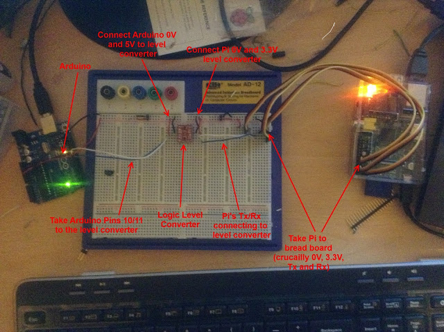
This is the circuit I built in photo form - very simple really. It's ultimatley just connecting the raspberry pi serial Rx/Tx to 2 pins on the arduino, however to avoid circuit damage there's a logic level converter in the middle.


I'll upload a circuit diagram if I manage to get visio up and running again!

Note: In case you didn't know, with basic communications stuff,  'Tx' means 'transmit' and 'Rx' means 'receive'. The idea is to connect the 'Tx' of one device into the 'Rx' of another and visa versa so they can chat!

The Pi on the right looks slightly more complex than it needs to as I didn't have any single wire jumper cables. So while I've connected 9 actual pins to the breadboard, I'm really only using:
  • Pin 1: 3.3V, connects to LV (low voltage) on the level converter
  • Pin 6: 0V, connects to GND on level converter
  • Pin 8: UART Tx, connects to Tx1 on level converter
  • Pin 10: UART Rx, connects to Rx0 on level converter
The Arduino is very similar:
  • 5V goes to HV (high voltage) on the level converter
  • GND goes to GND on level converter
  • Pin 11 (using for software serial Tx) connects to Rx1 on level converter
  • Pin 10 (using for software serial Rx) connects to Tx0 on level converter
I highly recommend testing the circuit with a voltmeter as you go. I verified the raspberry pi 0V/3.3V signals with a multimeter, and as you can see here, used an oscilliscope to check the serial port output was happening:


I won't declare that's necessary, but it helps to be sure. You can test all points of your circuit with it, and check that 3.3V is what will be pumped into your Raspberry Pi before actually making the final connections.

Arduino Program

This is the very basic program used on the Arduino. It's just checking for data from either the PC (on hardware serial port) or Raspberry Pi (on the software serial port via pins 10 and 11).

#include <SoftwareSerial.h>

SoftwareSerial mySerial(10, 11); // RX, TX


void setup() {
  // initialize hardware serial (arduino<->pc) and softare serial (arduino<->pi)
  Serial.begin(57600); //pc at 57600
  mySerial.begin(115200); //pi at 115200
}

void loop() {
  //check for data from pi
  if (mySerial.available())
  {
    unsigned char val = mySerial.read(); //read pi data
    Serial.write(val);    //send pi data to the pc
    mySerial.write(val);  //also echo it back to the pi, so it shows up as you type it
  }
  //check for data from pc
  if(Serial.available())
  {
    mySerial.write(Serial.read()); //send pc data to the pi
  }
}

The only slight oddity here is that I echo any data from the pi right back at it (in addition to forwarding it to pc). This is just so I can conveniently view it on the raspberry pi console and verify things are working even without the PC itself connected.

Preparing The Pi

I'm literally just repeating what I found on this very useful page: http://www.irrational.net/2012/04/19/using-the-raspberry-pis-serial-port/ in this section. Basically, bits of the default Pi setup reserve the serial port for stuff like kernel debugging and console output. We just need to disable those and restart it.

First up, I log into the Pi over SSH (search the web for how to do this - its very easy), as this gives me access to it from my PC, rather than having to actually hook it up to a tv/keyboard.


Now backup the old command line file in case I want it back!
sudo cp /boot/cmdline.txt /boot/cmdline_backup.txt

Edit the command line file:
sudo nano /boot/cmdline.txt

Remove the references to ttyAMA0. In my case this left me with:
dwc_otg.lpm_enable=0 rpitestmode=1 console=tty1 root=/dev/mmcblk0p2 rootfstype=ext4 rootwait

Now edit the inittab file
sudo nano /etc/inittab

And comment out this:
2:23:respawn:/sbin/getty -L ttyAMA0 115200 vt100

Then finally, reboot:
sudo reboot

After rebooting I installed 'minicom' - a handy serial port utility:
sudo apt-get install minicom

And run it connecting to the serial port:
minicom -b 115200 -o -D /dev/ttyAMA0

Testing It

So, we now have:
  • An Arduino with my program on, connected to the pc with the serial monitor open
  • A Raspberry Pi running minicom (in my case connected to pc via SSH for ease of use)
  • A circuit that connects, via logic level converter the serial Rx/Tx of Raspberry Pi with pins 11/10 of Arduino
In theory, if you type in minicom, it should appear in the Arduino output, and visa versa! Here's a video to prove it - hope I didn't miss anything!


Thursday, 17 January 2013

Pi Time!

Well, it's been a while since I updated this blog, but I'm sick, the house is a mess, the washing needs hanging up and my fingers are sore from playing the guitar. So it's obviously time to set up my Raspberry Pi. I'm writing this as I go, so I may get half way through and realise it's broke. Lets hope I get all the way through.

Here's the bits - an sd card, an hdmi cable, a power lead and of course the Pi itself.

The basic bits for the Pi - hdmi cable, power, sd card and the board itself

USB keyboard/mouse is recommended, but all I have on hand is wireless ones so lets hope they still do the job. I'll face that when I come to it though - even if we just get things booting up it'll be a win!

First up, pick an OS from the raspberry pi site - I'm going for the Linux Debian release, named Raspbian. Downloading...

In the mean time, lets find out how to set it up from here. Note - respect to the authors here - both links are not broken, despite being from a 6 month old piece of paper.

Apparently the easiest way to do it, having acquired the disk image from the earlier link is to grab win32diskimage from here and use it to write the image to an SD card (which is plugged into my lap top):

Disk imager - used to create initialize the sd card ready for the PI
You gotta love a nice simple program for a simple task! With the imager running, SD card in and image at 50% it's time for some tea.

OK, tea made, image downloaded. Hitting run.... percentages clicking up.. 25% and still going.... Done.

Boot time. OK, my monitor doesn't have hdmi input. Guess we're going with tv for now.

And incorrect plug type. Thanks RS electronics. Fortunately I am the sort of person with many an adapter lying around the house...

Everything wired up and ready to go
Doesn't work. Fiddle with plug.... and Houston we have Pi!

Hurray! It begins to boot. Lots of text, no scary error messages.
Looks like wireless keyboard works, but only if I plug in the adapter post boot, or maybe in a specific socket. Not worked that out yet. Oh well, time to fiddle. Looks like there's a handy config tool that boots up first, so I'l click on all the options to see what they do.

The first interactive screen - a friendly config tool


  • Expanding partition to fill the whole card worked fine.
  • Setting the keyboard was a little ropey, but I've ended up with a working UK setup. 
  • Presented with a vast list of locales to generate, and seem to have chosen none of them. It's generated the en-GB one though so hopefully that'll do for now.
  • Time zone nice and simple if you know your own address. I do.
  • Memory split seems to be how much memory to give the GPU. Default is 64MB which will do for now.
  • Lets not overclock it thankyou very much.
  • SSH enabled as I'm sure I'll need it at some point
  • Yes we'll boot straight to desktop please.

And lastly, given it ain't online yet, I don't see much point in clicking update, so I'm going for Finish! Reboot complete and...

Booted up after initial config, works first time. We have a desk top.
Well bugger me it works. With wireless mouse/keyboard as well (that's the logitech K520 wireless keyboard, and M310 mouse it comes with). That was easier than opening a document in the latest version of MS Office. OK so most things are easier than opening a document in the latest version of office, but this was still really easy.

Next up - the interweb. My knowledge of Linux is around about 0, so this'll be a test of the OS as much as it is the Pi. The obvious first step is to plug it into my router though...

Turns out plugging it in was also the last step. No other steps needed. And there you have it - a preview of this blog post (before even being posted) on the Raspberry Pi. Very chicken/egg ish.

Raspberry Pi connected to the interweb and previewing this blog

Well, that was the easiest bit of setting something up that might turn out complex I've done in a long a time. One might even say it was easy as Pi (boom boom). I guess there'll be some updating to be done, but I've heard Linux is good at that.

Well done Rasperry Pi team. You truly are the kings of small $30 computers.

Now I just need to decide what to do with it - probably next post will involve web cams - hopefully 2 of them! Or an Arduino. Who knows.

-Chris